
Repairing a Tight Lego Motor
- Jim Ratti

- Dec 23, 2020
- 4 min read

If you read my previous post, you'll know I've been working on reconditioning a 20+ yr-old Lego Mindstorms set for my Godchildren. Today I decided to tackle one of the motors. It seemed to have a lot of internal friction, causing its power output to be significantly lower than the others in the set. The other motors in the set would spin freely and coast to a stop. This one was quite difficult to turn.
The motors are clearly not made to come apart, so I figured I'd have to be extra careful. However, I bought a couple of extra motors on eBay that were in decent shape, so I figured I didn't have anything to lose if I ruined this one.
The first thing I tried was lubricating it with WD-40. I discovered that the back came off the motor relatively easily, so I pried it off as shown here:


Sadly, a good spray of WD-40 made no difference - the motor was still quite hard to turn.
Since I couldn't get to the gears and bearings from this back side, and there were no other seams in the case, I knew I had to somehow slide the motor assembly out of the plastic case. I noticed that there were four melted plugs of plastic holding the metal frame to the gray plastic case.
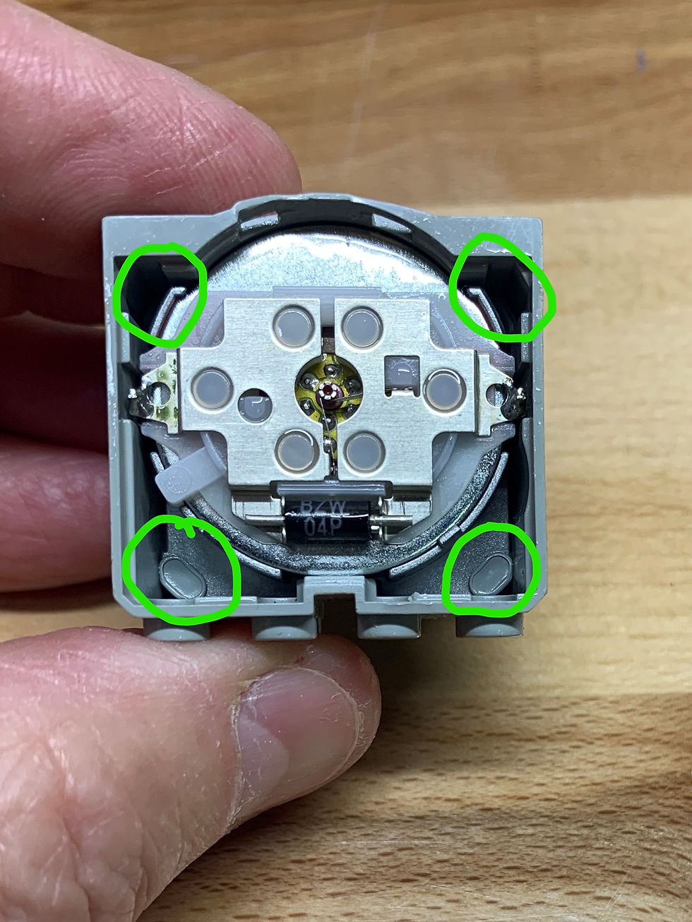
I didn't have a Dremel bit small enough to fit down into the two upper holes, but I found that a #49 drill bit would do the trick.

I carefully dug around all four posts and ground off the plastic on each.

The motor slipped right out of the case, along with the attached black electrical connector. Sweet!

Here you can see the four posts in the gray case. I reasoned that I could use a drop of epoxy on each during reassembly. I later changed my mind, as you'll see.

Now I had to figure out what was causing the friction. I couldn't see anything wrong with the gear train, but it seemed like the armature was dragging on something. It didn't appear to be rubbing the back side of the metal motor case, so it had to be either the armature bearing or the bearings for one of the gears. So, on to trying to disassemble the motor without destroying it.
First I unsoldered the connector from metal tabs on the white plastic plate on the back of the motor. The joints are very small and it only took a quick touch with my pencil iron to separate the joints.

Next I VERY carefully pried the white cover off the back of the motor. It's held in place by two small ears and a locating tang.

The ticklish thing here is that there are two sets of very fine spring wires that contact the commutator on the motor shaft. I had to be quite gentle to make sure I didn't damage them.

I discovered that the black bushing on the front half of the motor shaft popped right out. However, removing it didn't seem to make any difference - the motor was still tight.

I thought maybe I could get the armature out of the front bearing if I could get the metal plate off the back of the motor. It didn't seem to be bonded to the motor case, so I gently pried with a wide screwdriver and found that it came loose fairly easily.

There are permanent magnets in the motor that are quite strong, so I had to be careful when separating this backing plate to be sure I didn't let the magnets pull the plate back into the fine copper windings in the armature and damage them.

It looked like the armature shaft was being held in place by a friction fit into the black plastic bushing shown below. I wondered if a light tap with a small hammer might add just enough clearance to free up whatever was sticking.
So, I supported the motor case my laying it in the jaws of my small bench vise (no closing pressure, so as not to distort the case) and gave a few light, downward taps on the shaft.

The good news was that the armature now spun freely. The bad news was that I'd slipped the shaft too far down on the bushing, and there was excessive end play in the armature shaft. When I reattached the back metal plate, I found that the armature would contact the plate. So, I removed the metal plate again and used a 17mm socket to support the back of the armature. The magnets in the motor held the socket firmly in place.

I used a small drift punch to very gently tap the black bushing a bit further down onto the armature shaft.

After a bit of trial and error, I got the clearance just right. The motor spun freely but didn't contact the back metal cover.
I replaced the metal backing plate and the white plastic piece on the back of the motor, being careful to correctly place the commutator brushes. Then I re-soldered the connector wires.

I tested the motor by applying 9 volts from my bench power supply and was pleased to see that the motor ran perfectly.

I reassembled the motor by slipping it and the connector back into the gray housing and snapping the plastic back on. I decided not to epoxy the motor into the case because I found that the plastic back alone held everything in place just fine. That way, if I ever have to pull this motor apart again, I'll be able to do so without drama. Another test run using the power supply confirmed that all was in order.
In conclusion, these are the kinds of projects I love doing at Jim's Workshop. I didn't really know how this would turn out, but I was curious enough to want to give it a try. And since I had other motors that worked acceptably well, I figured I had nothing to lose. So, a 20 yr-old toy lives on to educate another generation. What's not to like about that??
Let me know what I can fix for you!


Comments